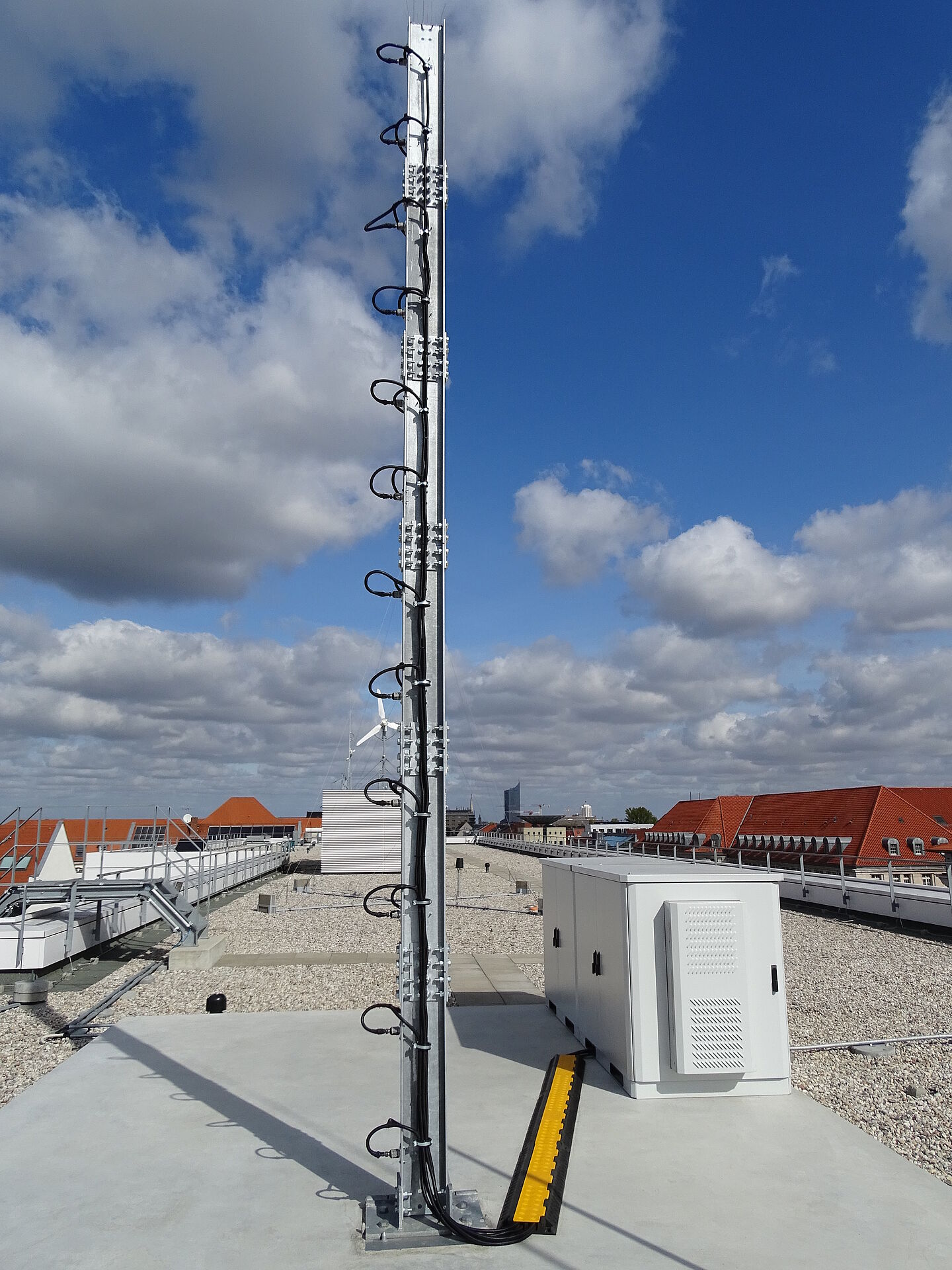
The test structure produced on an open air test facility on the roof of the Nieperbau
The I4S is developing methods for identifying the condition of mechanical structures in the maintenance phase (e.g. localization of structural changes). The methods are verified using real measurement data from ambient excited (wind, traffic, microseismic, etc.) mechanical structures. For this purpose, the I4S has two identical, modular test structures in the Laboratory for Structural Dynamics and on an open-air test facility on the roof of the Nieperbau at the HTWK Leipzig. The development and production of these test structures is described below.
Requirements
For the application of developed methods, the consideration of environmental conditions (e.g. temperature, humidity, wind strength and direction) is an important research topic. For this reason, an identical structure was planned under controllable and uncontrollable environmental parameters, in the laboratory and in the field. Ambient structural excitation is realized by means of wind and microseismics.
A modular design was necessary to set up and dismantle the test structures as required. Furthermore, it was also planned to verify methods developed for localizing structural changes on the test objects, whereby reversible structural modifications (masses and stiffnesses) were required. Based on these requirements, a design was selected which is described below.
The test structure
A test structure was chosen which consists of six 1m long modules bolted together (total length 6m, see Figure 1). An important element of the modular structure is the possibility of reversibly applying changes in mass and stiffness with the aid of additionally bolted steel elements.
A rolled profile with an IPE200 cross-section of steel grade S355J2 (DIN 1025-5) was used to provide static proof of stability. Relevant design parameters are therefore E = 21,000 kN/cm², Iy = 1940 cm4 and Iz = 142 cm4. The flange and web connections were made with bolted straps (ø16 bolts of strength class 8.8, see Figure 2). A gap of 1 cm between the profiles was realized. Furthermore, the screw connections are adapted to the cross-section values of the selected profile (Iy=1931 cm4 and Iz= 143 cm4).
Construction of foundation
A suitable installation site was sought for the planned test structure in the open field, a 6 m high mast in an exposed location. The location on the roof of the Nieperbau proved to be ideally suited due to its exposed position and easy accessibility. However, the flat roof (see Figure 2) had only been designed for a load from additional experimental fields in some areas. Therefore, an appropriately adapted foundation had to be constructed for the planned experimental setup.
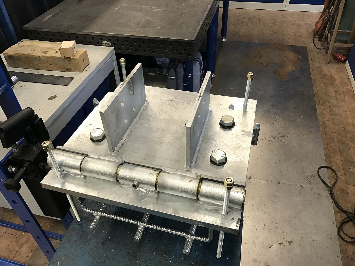
The planned structure was built on a reinforced concrete slab to ensure stability. To limit the load on the roof, the foundation is made of lightweight concrete of class LC30/33 (bulk density class 1.4; outer component concrete cover 4 cm). A base plate Bl25 with 50x50 cm of the test structure with connecting reinforcement was positioned on the installed reinforcement. The base plate was manufactured in the workshop of the HTWK Leipzig. The design included a ø40 mm bearing bolt so that the mast could be brought into a horizontal position if required (application of sensors, etc.) (see Figure 3). The foundation slab is 5x10 m in size and was concreted directly onto the roof insulation (with a slope of 2-5%). The minimum thickness of the foundation is approx. 20 cm.
The other technical equipment required for the experimental field included lightning protection and an outdoor server cabinet with connection to the faculty network. The state of Saxony has provided funding for this.
Construction of test structure and experimental investigation
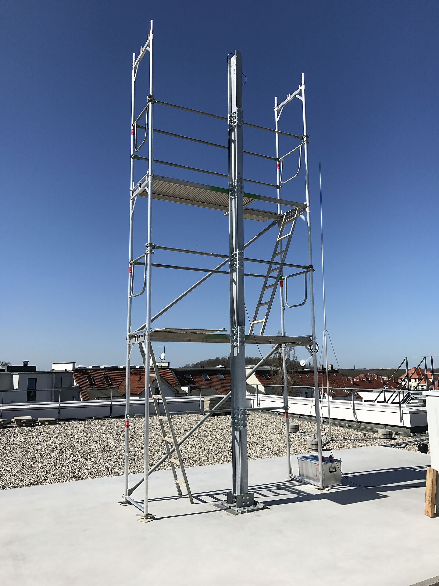
The described modular, approx. 6 m high test structure was erected on the prepared foundation. The 25x14 cm base plates Bl12 are attached to the first segment of the mast with four bolts each and four base bolts ensure that the tensile forces are transferred to the steel plate set in concrete. At the time the test structure was erected, all bolts were preloaded to 200 Nm.
The test structure is excited to vibrate as a result of ambient excitation (wind, microseismic). This structural response behavior is recorded with 24 uniaxial piezoelectric accelerometers at equidistant intervals (393A03, PCB Piezotronics). A weather station, which measures wind speed, direction, humidity and temperature, was also installed. This provides the I4S with an excellent test structure in an exposed location, which is used for method verification and subsequent publication of the results (see Figures 5).


